Example Ejector Pump Installation
Here is an example of the Sensor Monitor installed on a duplex ejector pump system.
DISCLAIMER: This installation may not be compliant with applicable building codes and may be unsafe. It is up to the user to determine how to install this product to meet their needs and to ensure that any installations are safely done and in compliance with any applicable building codes. It is suggested that a licensed electrician be hired for any installations. The Sensor Monitor is not intented to be an alarm system rather it is indended to monitor the pump operation and inform the user of conditions that may be or could lead to problems.
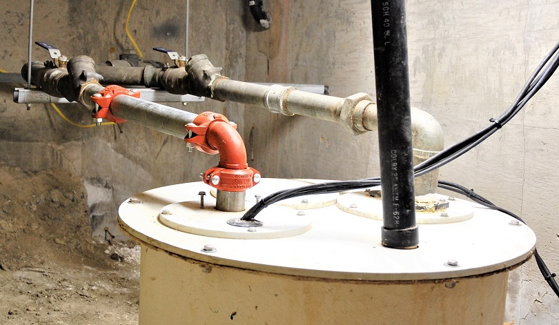
This system uses a pair of Zoeller E284 1hp 240v pumps connected to a PSI control system. There are three float switches to control the pumps which are the duplex standard off, on, and lag. A high level switch that is connected to the building security system and will trigger if the tank level rises too far above the lag pump activation mark is also used.
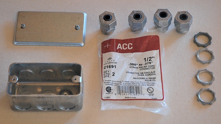
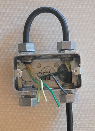
A 4" x 2" standard junction box, four strain relief cord connectors, and a cover are used to create a current monitoring loop for each pump.
The cable from the control box is trimmed as shown.
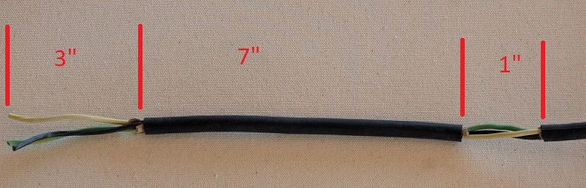
One of the hot conductors is then removed from the jacketing at the 1" section. The cable then enters thru one of the strain reliefs, the section with the missing hot exits the box and loops arround and back in. The pump is then connected to the box through the remaining strain relief and all of the conductors are secured with wire nuts. Notice the box has been grounded.
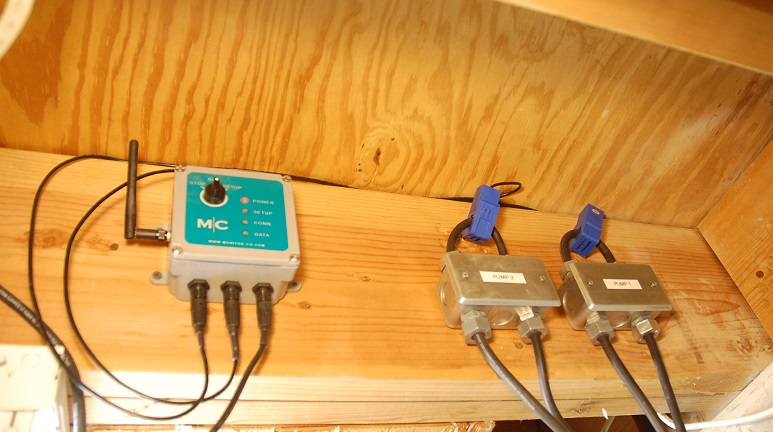
The Sensor Monitor is attached to the overhead basement floor joist adjacent to the junction boxes. The current sensors are placed over the wire loops. The wi-fi access point is in the next room on the upper level. The Sensor Monitor can be plugged into any standard USB source of power (not included with the Sensor Monitor). It is reccomended that a UL listed high quality USB power supply be used with the Sensor Monitor.
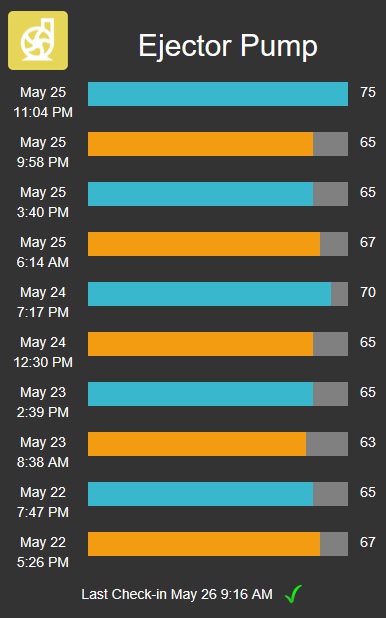
An account was set up for this Sensor Monitor device and the Ejector Pump panel was added to the dashboard. This panel will show the last 10 pump runs with alternating color bars depending on the activated pump. If the lag pump was activated that portion of the run is shown in red. The date and time that the run started are shown as well as the duration. After the runs have been observed for some time and the typical characteristics determined alerts can be set on the device panel for abnormal conditions that could predict future problems.
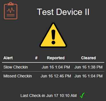
The Alert and Status panel was also added to the dashboard. This panel shows a green-yellow-red type indication of any alerts that have been set up for the device as well as a 24 hour alert history. In this case the yellow caution symbol is displayed becuase the device has had an alert in the last 24 hours. It happened to be a connectivity alert which has been cleared. If there are any non cleared alerts a red warning symbol is displayed. Alert notifications are also emailed after they occur.